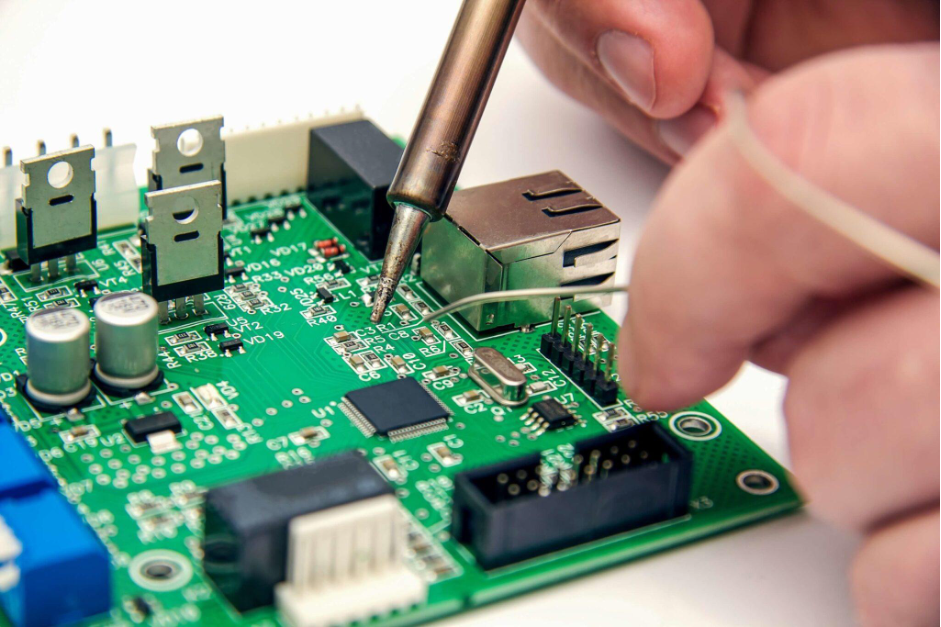
Modern technology thrives on high-speed connections that deliver lightning-fast results and data transfer rates. The need for high speed has been a norm in every possible sector that is directly or indirectly related to electronic devices. There is a separate framework that goes into place to achieve high-speed PCB designs that are capable of passing through a large amount of data at an extremely fast speed. The circuit designs vary might in different applications as there is more than one factor involved in the delivery of high speeds in different cases.
When we talk about the delivery of high speeds from a technological point of view, then it's essential to know that there are two main categories in which the PCB designs are categorized. The categories are known as digital and analog, each of them coming with its own sets of principles, benefits, and cons. The analog designs have the ability to transmit the data at a radio frequency, whereas the digital ones work by relying on the signals that are transmitted within the framework of the device. When we talk about digital designs, there are different elements that need to be addressed, including the frequency, number of transistors present in a device, and the combinations that allow the devices to produce results at a given time period.
The positive impact of the fast speed that the PCBs provide can't be denied, but there have been some repetitive issues that have been noticed at various points that often interrupt the liquidity that is required from a PCB board connection. There have been cases where the logic gates have not been given the required time to settle. The probability of this increases when the buffer delay is greater than the speed. There have been different efforts to overcome this malfunction, but still, this issue upholds the true potential of the PCB circuits.
The factor that largely dictates the outcome in a PCB connection is the syncing of the data signal and the clock. If there is an attempt that is planned to be unusual, then it might cause severe damage to the system, and in some cases, it might cause a system failure.
The connections present in a PCB setting should be perfectly functioning because if any connection is not connected as it should be, then it might lead to factors such as short-circuit.
The speed of the high-speed signal is primarily defined by its rising/falling edge. Another factor in this is the ratio between the rising/falling period and the transition speed running through the system wires. The core idea behind this is that a PCB will be considered as a high-speed compatible mechanism if the delay on the wire is more than a quarter of the rising/falling period.
The PCB designs are mainly complicated, with several challenges occurring during each application. There are different phases that need to be considered to minimize the possibility of any potential error that might cause problems with the original design. The steps start from the very beginning, where the PCB designers have to find workable patterns that are not only efficient but capable of delivering high speed. When we talk about the second phase of the PCB modules, then it's important to know that in this particular phase, the PCB designer follows the constraint settings with unique high-speed routing functionality.
Lastly, when the layout is ready to be used in its full functionality, the pattern goes through extensive quality assurance measures to check all the norms required for signal integrity. When we are talking about the circuit board assembly manufacturer market, then it's a known factor that the manufacturers ensure that all the required protocols are followed to achieve workable high-speed PCB circuits.